Application Interface
The Tutorials (a separate document) contain a tutorial that leads
you through the RISAFloor interface with an actual
model. Consider going through the tutorial if you have not done
so already, as it is the fastest way to learn the program. Although
it requires some time up front, the tutorial will save you time and brainpower in
the long run.
The features that are available to you in RISAFloor may be accessed through
the main menu, shortcut menus, toolbars and shortcut keystrokes. You may use any or all of these vehicles to interact with the software.
The main menu has the advantage of containing all of the program options and features and may
initially be the simplest to use, letting you learn just one system.
The toolbars contain more common options and invoke with one click.
The shortcut menus present options relevant to the task at hand.
The shortcut keys provide a fast way to access features should you use
the program often enough to help you become familiar with them. All of these
features are discussed in the sections below. There are many ways
to access features and the method that you will use will simply be a matter
of personal preference. The good news is that you have the options.
The bar along the top of the screen is called the title bar and contains
the name of the file that is currently open. The three buttons  on the far right side of the title bar are
used to control the main window. The left button will shrink the
main application window to a button on the taskbar. The middle button
will shrink or maximize the window on your screen. The right button
will close the window, prompting you to save changes if necessary.
You will also see these buttons in other windows and they have basically
the same functions there as well.
on the far right side of the title bar are
used to control the main window. The left button will shrink the
main application window to a button on the taskbar. The middle button
will shrink or maximize the window on your screen. The right button
will close the window, prompting you to save changes if necessary.
You will also see these buttons in other windows and they have basically
the same functions there as well.
The actual work that you do will be in the main area on the screen,
which is called the workspace. When you open a model view, a spreadsheet
or a dialog it will be opened in the workspace and listed in the Window
menu. You may have as many windows open as you like.
Main Menu
All of the program features may be accessed through the main menu system at
the top of the screen beginning with File on the far left and ending
with Help or possibly Director on the far right. Clicking on each of these
menus (listed below) will display sub-menus that contain options that
you may choose from. You may also select the main menus by using
the ALT key along with the underlined letter in the menu you wish to choose.
You may then continue to use the keyboard to choose from the menu options.
In addition, some of the menu options will have hot key combinations
listed to the right of the option. These hot keys allow you to
use the keyboard to access features without using the menu system.
File Menu
New will close the current file, prompting
for saving if necessary, and will open a new file.
Open will close the current file,
prompting for saving if necessary, and will open an existing file.
Save will save the current file, prompting
for a name if necessary.
Save As will save the current file,
prompting for a name.
Import DXF File will
create a new floor using
an existing DXF file.
Export will export the current file
to a DXF or SDNF file.
For more information on the interaction between RISA and other programs refer to Appendix E.
Print will access RISAFloor printing options.
Page Setup will present page setup
options for printing.
Recent Files The five most recent
files will be listed at the bottom of the menu. Selecting one of
these files will close the current file, prompting for saving if necessary,
and will open the selected file.
Exit will close RISAFloor, prompting for saving if
necessary.
Edit Menu
Undo will undo the last edit that
was applied to the model whether it was made graphically or in the spreadsheets. You may continue to apply Undo to remove up to 100 model edits.
Redo will reverse the last undo that
was applied to the model. You may continue to apply Redo
to remove up to 100 undo operations.
Select Allwill highlight an entire spreadsheet all at once.
Copy will copy the selected spreadsheet
cells or model view from the active window to the clipboard.
Paste will paste data from the clipboard
to the spreadsheet cells.
Insert Line will insert a new line
in the spreadsheet beneath the current line.
Delete Line will delete the current
spreadsheet line.
Repeat Line will insert a new line
in the spreadsheet beneath the current line and copy the data from the
current line.
Mark All Lines will select all of
the lines in the spreadsheet.
Unmark Lines will unmark any currently
marked lines.
Delete Marked Lines will delete the
marked lines in the spreadsheet.
Find will locate an item on the spreadsheet
by its label.
Fill Block will fill the marked block
of cells with a valid entry.
Math on Block allows you to add, subtract,
multiply or divide the values in the marked block of cells.
Settings
Settings
opens the Model Settings.
View Menu
New View will open a new model view
window.
Save or Recall Views allows you to
save a view or recall a view that has previously been saved.
Clone View makes a copy of the current
view so you can modify one and maintain the other.
Refresh All will refresh all of the
windows that are open in the workspace.
Select provides graphic select options
that are also provided on the Selection Toolbar.
Unselect provides graphic unselect
options that are also provided on the Selection Toolbar.
Save or Recall Selection States allows you
to save a selection or recall a selection that has previously been saved.
Zoom provides options for zooming
in and out of the current model view.
Rotate provides options to snap the
model view to global planes or an isometric view.
Model Display Optionsopens the Model Display Options.
Render will turn rendering of the current model view on or off, depending on the current setting.
Drawing Grid will turn the display of the Drawing Grid on or off, depending on the current setting.
Project Grid will turn the display of the Project Grid on or off, depending on the current setting.
Axes will turn the display of the global axes
in the model view on or off, depending on the current setting.
Loads will turn the display of the model loads on or off, depending on the current setting.
Point Labels will turn the display of
the point
labels on or off, depending on the current setting. A third setting is also available where the points themselves are not shown at all.
Beam Labels will turn the display of the
beam
labels on or off, depending on the current setting. However, if rendering is turned on, beam labels will not be visible in the model view.
Insert Menu
The Insert Menu will help you insert new items into the model.
Most of the options will provide a graphical method of insertion but some will open
spreadsheets where appropriate. See Graphic
Editing for specific information.
Modify Menu
The Modify Menu will help you modify existing items in the model.
Most of the options will provide a graphical method of modification but some will open
spreadsheets where appropriate. The Delete Items Dialog may also be accessed via this menu. See Graphic
Editing for specific information.
Spreadsheets Menu
The Spreadsheets Menu provides access to any of the input spreadsheets. See
Spreadsheet Operations to learn
how to work within the spreadsheets.
Solve Menu
Clicking on the Solve Menu will immediately begin a solution to the model. See Solution
for more information.
Results Menu
The Results Menu provides access to any of the results spreadsheets. See
Results
Spreadsheets for more information.
Tools Menu
Delete
All Unattached Points will delete any points that are not connected
to beams, columns, decks, deck edges or loads.
RISA-3D
Data will allow you delete selected portions of the RISA-3D model
that automatically generated by Floor. It
will also allow your to "re-start" the optimization of member
sizes based on the current RISAFloor sizes.
Relabel Column Stacks assigns new labels to the column stacks in their
current order in the Column Stacks spreadsheet.
Round
Off Point Coordinates will round off the coordinates.
Delete all Wall Panel Regions will delete the regions on all wall panels. The regions will be automatically regenerated next time the model is solved.
Full Model Alignment will shift the coordinates for each floor to align all the vertical elements.
Application Settings contain settings that
let you customize the program. See Customizing
RISA for more information.
Customize Toolbar allows you to modify the model view toolbar by adding, subtracting and re-ordering buttons. See the customizable toolbar section.
Reset All Program Defaults will reset all customized settings to the original factory settings.
Window Menu
In order to help you work with the model and the results, you are provided
with many window arrangements to choose from. You may access them
from the Window Menu. The best way to understand just what
these 'tilings' do is to try them. Remember that once you choose a
tiling you may adjust any of the windows as you wish.
Help Menu
Help Topics opens the RISAFloor Help File so
that you may search the contents and the index. See Help
Options to learn about getting help.
Check for Update runs an internal check for possible program updates. If your program is up to date, you will receive a message saying you are up to date. If you are out of date, the check will offer you the option to email RISA Tech, Inc. for upgrade information if you are out of date for a major update. If you are out of date just a minor update, then we will send you to our website to upgrade.. This check is also offered during the installation process.
Upgrade to RISAFloor ES: If you do not currently own the Elevated Slab portion of RISAFloor (called RISAFloor ES) then purchasing it will allow you to enter in an RUS password to make it available in your program. See the Elevated Slabs - Overview topic for more information.
Licensing gives information about your subscription license and the option to Borrow or Return a license from your subscription.
About provides RISAFloor version and hardware
key information.
Director Menu

If you are working from within the RISA Building System (RBS), use this menu to switch between
RISAFloor, RISA-3D and RISAFoundation. If you are not working within the RISA Building System, the Director Menu will not be shown. See RISA-3D Integration for more information.
The directory button is located at the far, far right hand side of the Main Menu Toolbar as shown in the image above.
Shortcut Menu
The Shortcut Menu is also referred to as the Right-Click
Menu. This is because to access the shortcut menu you simply click
the RIGHT mouse button where you are working to see options that are relevant
to what you are doing. For example if you are working in a model
view the right click menu will provide options to help you modify the view or edit the model graphically. If you are working in a spreadsheet
the menu will provide editing tools for that spreadsheet.
This menu will appear wherever you RIGHT click the mouse. This
way you do not need to move away from where you are working to select
the features you want to use.
Toolbars
The Toolbars provide buttons to help you access common commands and
popular options in the menu system discussed above. There are different
toolbars that will appear as you work to build your model and browse your
results. If at any time you are not sure what a particular button
does, simply let your mouse hover over the button and a helpful tip will
pop up and explain the button.
RISA Toolbar

The first horizontal toolbar located just below the Main Menu
is called the RISA Toolbar. The buttons on this bar
facilitate file and window access. You may use these buttons to
open files and windows and also to analyze the model.
Window Toolbar


The Window Toolbar is the second horizontal toolbar located below the Main Menu.
It gets its name because the buttons change as you move from window to
window in order to help you with what you are currently doing. When
you are working in a model view the buttons provide viewing tools, such
as Rotate and Zoom, to assist you with that view. There are also many other results and information display toggles, including some icons with the drop down arrow next to them. Clicking the arrow will show you the different view options for that icon. Clicking the icon itself will bring you back to the default view. Note that this model view toolbar is now fully customizable. See below for more information.
Other model view windows that are open will not be affected so that each
may show different information. When you are working in a spreadsheet,
editing tools are provided that are appropriate to that particular spreadsheet.
Note that not all tools are available with all spreadsheets. In
fact there are many tools that are provided for one spreadsheet only.
See Spreadsheet Operations for
more information.
Customizable Model View Toolbar
The model view toolbar is fully customizable. By creating your personalized toolbar, you can quickly access your most frequently used buttons. This can be done quickly and easily in just a few steps.
- Go to Tools menu and select Customize Toolbar.

- Select one of the toolbars by clicking in the box Available toolbar buttons, and click on Add to place them on the current toolbar.
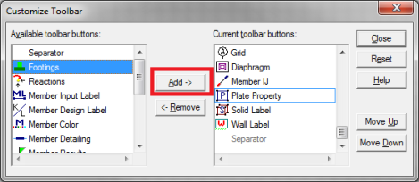
- Once you’ve moved the buttons to the Current Toolbar, you can rearrange them by clicking on Move Up or Move Down.
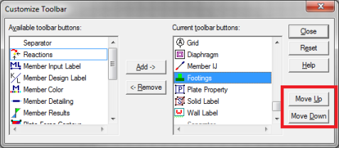
- Click Close and you will see your selections on the model view toolbar.
Note:
- You must have a model view as the current view to see this toolbar.
- If you add more buttons than will fit on the toolbar the buttons that are at the end of the "Current toolbar buttons" will be cut off.
- The changes you have made will automatically be saved on a per-user (Windows User) basis, such that next time you open the program the toolbar will be arranged per your Application Settings. These saved changes are saved in the registry in the HKEY_CURRENT_USER\Software\RISA Technologies\RISAProgram location with a String Value called "ToolbarState".
Selection Toolbar
The vertical toolbar on the left side of the screen is the Selection
Toolbar. This toolbar will only be available when the active
window is a model view. The buttons on this toolbar help you select
and unselect items in the model in order to help you build and modify
the model or view results. See Graphic
Selection for more information.

Drawing Toolbar
 (beam floor)
 (slab floor)
Another toolbar that is available is the Drawing Toolbar. Unlike
those mentioned above, this toolbar is located in the model view windows
rather than in the main application window. This way the drawing
tools stay close to where you are working. This toolbar controls
modeling features that help you draw, load, and modify your model graphically.
You may have more than one view open and a Drawing Toolbar for each view.
This way you can simultaneously draw columns in one window and beams
in another.
The Drawing Toolbar may be displayed in any model view window
by clicking  on the Window Toolbar
while in the model view window. Some of the buttons on the toolbar
are for one-time applications such as modifying the drawing grid. Other buttons place you in an editing mode, such as Draw Columns, that remains active until
you cancel it. The current mode is indicated by the mouse pointer
and by the state of the button. While in an editing mode the button
will stay down until you click it again or choose another button.
See Graphic Editing for more information.
on the Window Toolbar
while in the model view window. Some of the buttons on the toolbar
are for one-time applications such as modifying the drawing grid. Other buttons place you in an editing mode, such as Draw Columns, that remains active until
you cancel it. The current mode is indicated by the mouse pointer
and by the state of the button. While in an editing mode the button
will stay down until you click it again or choose another button.
See Graphic Editing for more information.
This brings us to an important point. Some of the toolbar buttons
remain down when you press them to indicate that you are in a certain
mode or that something is either on or off. For example the Box
Zoom  button will stay down to indicate
that you are currently in the zooming mode. The Show Drawing
Toolbar button will remain down when
you turn on this toolbar for the active window. You may be in more
than one mode at the same time as long as they are not mutually exclusive.
button will stay down to indicate
that you are currently in the zooming mode. The Show Drawing
Toolbar button will remain down when
you turn on this toolbar for the active window. You may be in more
than one mode at the same time as long as they are not mutually exclusive.
|
|
|

|
| RISAFloor Data Entry |
RISAFloor Results |
RISAFloor ES Data Entry |
RISAFloor ES Results |
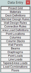
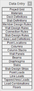
The Data Entry Toolbar is the
vertical toolbar on the right side of the application window. It
contains buttons that facilitate data entry through the spreadsheets.
The buttons on this toolbar provide quick access to the spreadsheets that
are also listed in the Spreadsheets Menu. You may open and
close the toolbar by clicking the  button
on the RISA Toolbar.
button
on the RISA Toolbar.
Note
- Depending on whether you own RISAFloor ES or just RISAFloor, the Data Entry and Results toolbars will be different.
For additional advice on this topic, please see the RISA Tips & Tricks webpage at risa.com/post/support. Type in Search keywords: Data Entry.
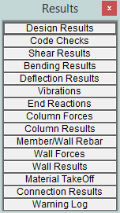
The Results Toolbar is the vertical
toolbar on the right side of the application window that is placed over
the Data Entry Toolbar after the model has been solved. The
buttons on this toolbar provide quick access to the results spreadsheets
that are also listed in the Results Menu. You may open and
close the toolbar by clicking the  button
on the RISA Toolbar.
button
on the RISA Toolbar.
Dynamic View Controls
When your current window is a graphical model
view, you can use the mouse wheel to dynamically zoom, pan, or rotate
the graphical image.
| Mouse Action |
Model View Function |
|
Rolling the Wheel Forward
|
Zoom In
|
|
Rolling the Wheel Backward
|
Zoom Out
|
|
Clicking and holding the Wheel Button
|
Grab the image and pan in the direction of mouse movement
|
|
Click and hold the Wheel button while pressing the Shift
key
|
Dynamically rotate the structure in the direction of
mouse movement
|
Dynamic Pan:
Clicking and holding the mouse wheel button triggers the tool and allows
the user to pan or drag the view to the limit of scroll bars.
Dynamic Zoom:
This tool uses the wheel button on the mouse. Rotating forward zooms in
and rotating backward zooms out.
Dynamic Rotate: This tool is
triggered by clicking and holding the mouse wheel button while holding
the Shift key. The rotational movement will be based on the how the user
drags the mouse cursor over the screen and the projection of theglobal axis
on the screen. For rotation about X axis, drag the cursor perpendicular
to the projection of the global X axis. The same logic applies for Y or
Z axis rotations. When rotation is initiated, the system locks for rotation
about that axis until the user releases the middle mouse button.
Zoom Previous/Next:
Function keys F3 and F4 are associated with Zoom Previous and Zoom Next
respectively. The system holds a doubly linked list of zoom info. This
list has 10 zoom-states in the list. The F3 or F4 keystroke moves the
active pointer forward or backward on the list. Each window has its own
zoom list.
Dynamic Distance
Tool: This tool triggers by pressing the F5 key. The user has to
pick up two points on the screen and the system gives back the total and
partial distance between points on the status bar.
Shortcut Keys and Hot Keys
Shortcut Keys and Hot Keys allow you to use the keyboard to quickly
access features. The difference between the two is simply that the
shortcut keys are related to a specific window and will only work in that
window while the hot keys will perform at most any time.
General Hot Keys
| Key Combination |
Function |
|
F1
|
Help on the active window
|
| F5 |
Activates the Dynamic Distance Tool |
|
Ctrl-F1
|
Main Help topics
|
|
Ctrl-F2
|
Create New view
|
|
F7, Ctrl-F7
|
|
|
Ctrl-C
|
Copy to the clipboard
|
|
Ctrl-V
|
Paste from clipboard
|
|
Ctrl-N
|
Start a new file
|
|
Ctrl-O
|
Open an existing file
|
|
Ctrl-S
|
Save the current file
|
|
Ctrl-P
|
Print
|
|
Ctrl-Z
|
Undo
|
|
Alt-
|
Access the menus by combining the Alt key with the underlined
letter in the menu
|
Shortcut Keys available for Specific Windows
| Key Combination |
Model View Window |
Spreadsheet |
|
B
|
Open Draw Beams Dialog
|
|
|
C
|
Open Draw Columns Dialog
|
|
|
W
|
Open Draw Wall Panels Dialog
|
|
|
I
|
Open Draw Infill Beams Dialog
|
|
|
D
|
Open Create Diaphragm Edge Dialog
|
|
|
S
|
Open Draw Slabs Dialog
|
|
|
O
|
Create Slab Openings
|
|
|
K
|
Open Assign Deck Dialog
|
|
|
M
|
Move Selected Part of the Model
|
|
|
N
|
Copy Selected Part of the Model
|
|
|
E
|
Extend
|
|
|
T
|
Trim
|
|
|
L
|
Toggle Loads Display
|
|
|
,
|
Show Wireframe or Rendering View
|
|
|
.
|
Show Node Labels
|
|
|
/
|
Show Beam Labels
|
|
|
`
|
Lock View
|
|
|
Delete
|
Open Delete Items Dialog
|
|
|
R
|
Open Detail Report
|
|
|
Shift-A
|
Draw Area Loads
|
|
|
Shift-L
|
Draw Line Loads
|
|
|
Shift-P
|
Draw Point Loads
|
|
|
Ctrl-D
|
Open last graphic editing dialog
|
Delete Marked Lines
|
|
Ctrl-G
|
Toggle Drawing Toolbar
|
|
|
Ctrl-A
|
Select All
|
Select All
|
|
Ctrl-U
|
Unselect all
|
|
|
Ctrl-F
|
|
Block Fill
|
|
Ctrl-M
|
|
Block Math
|
|
Ctrl-I
|
Invert Selection
|
|
|
Ctrl-L
|
Toggle Lock unselected
|
Unmark lines
|
|
Ctrl-Enter
|
|
Press cell  button button
|
|
F2
|
Open Model Display Options
|
Start/Stop Cell Edit
|
|
F3
|
|
Insert line
|
|
F4
|
|
Delete Line
|
|
F5
|
Initiates the "Distance" tool
|
Find
|
|
F6
|
Initiates the "Area Load Query" tool
|
|
|
F8
|
|
Repeat Current Line
|
|
+
|
Zoom In
|
|
|
-
|
Zoom Out
|
|
|
!"#$
PgUp PgDwn
|
Scrolling
|
Scrolling
|
Spreadsheet Hot Keys that open spreadsheets
| Key Combination |
Unsolved Model |
Solved Model |
|
Ctrl-Alt-C
|
Point Coordinates
|
Column Results
|
|
Ctrl-Alt-D
|
Line Loads
|
|
|
Ctrl-Alt-E
|
Beams – Primary Data
|
Deflection Results
|
|
Ctrl-Alt-F
|
|
Bending Results
|
|
Ctrl-Alt-G
|
Model Settings
|
|
|
Ctrl-Alt-H
|
|
Design Results
|
| Ctrl-Alt-J |
Wall Panel Rules |
|
| Ctrl-Alt-K |
|
Solid Stresses |
|
Ctrl-Alt-L
|
Load Combinations
|
|
|
Ctrl-Alt-M
|
Materials
|
Material Take Off
|
|
Ctrl-Alt-N
|
|
Concrete Reinforcing
|
|
Ctrl-Alt-P
|
Point
Loads
|
|
|
Ctrl-Alt-R
|
Design Rules
|
End Reactions
|
|
Ctrl-Alt-S
|
|
Shear Results
|
|
Ctrl-Alt-U
|
Seismic Design Rules
|
Design Results
|
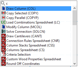
Search Bar

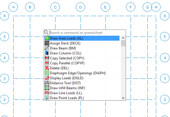
The Search Bar provides a quick access to commands and spreadsheets by searching their full names or shortcuts. The Search Bar can be accessed by either clicking the  button in the RISA Toolbar, or pressing the Space key on the keyboard when in an active model view. Users can use the Enter key to confirm the selection of the search results. This will close the Search Bar and bring up the corresponding dialog or spreadsheet. Users can also use the Up or Down Arrow keys or hover the Mouse over different search results to move the selection. After the search bar is prompted, users can press theEsc key at any time to exit the search bar. The search bar will always be prompted at the center of the active model view window. Once the Search Bar is prompted, the program will hide other active dialogs or spreadsheets to give focus to the search bar. Pressing the Esc key will exit the search bar and regain access to the hidden dialogs or spreadsheets.
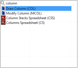
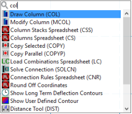
In the search bar, users can search either the full names or shortcuts of commands or spreadsheets. For example, typing either "Column…" or "COL" will locate the Draw Column (COL) command. The search results are displayed dynamically as users type, and the best match is highlighted at the top of the list. The search bar remembers recent search results and displays them at the top of the list. The most recent search results are always displayed first, making it easier for users to access their most frequently used commands or spreadsheets. Shortcuts for commands and spreadsheets can be learned from the parentheses in the search result display. For example, most spreadsheets use their acronyms as the search shortcuts. Users can type "CCS" to quickly locate the Code Check Spreadsheet instead of typing the full name, "Code Check...".
Accessing commands or spreadsheets through the Search Bar behaves the same way as clicking the buttons or spreadsheets from the application interface. For example, clicking the  button multiple times will switch the display between wireframe and rendering view. Accessing the same tool from the search bar will behave the same way. The memory feature that saves the last search results at the top makes it easier to access the same command repetitively. Users can quickly press Space and Enter to mimic the toggling behavior of clicking a button. Overall, the search bar is a powerful tool that makes it easier for users to find and access commands and spreadsheets quickly and efficiently in RISA.
Status Bar

The Status Bar passes useful information to you as you work. It
is divided into four parts located along the very bottom of the main application
window, just beneath the workspace.
The left side of the status bar shows a solution flag to indicate the
solved state of the model as follows:
| Solution Type |
Unsolved |
Solved |
|
Static
|

|

|
After a solution has been performed
and modifications are made to the model, the “S” icon changes to  (yellow). This indicates that the model has been solved but then modified
To the right of the solution flags there
are three message boxes.
The first and largest box lets you know what you are currently doing.
If you are in a spreadsheet, this box will contain the explanation of the
current cell. If you are working in a model view and select a graphic
editing option, look to this box for information on how to use the feature.
The second box is used to pass you units of the current spreadsheet
cell.
The third box indicates the coordinates of the mouse when a model
view is active. The mouse coordinates that are displayed are the
coordinates of the grid point or joint that is nearest to the mouse.
Windows
Modeling the structure will take place within model views and spreadsheets,
each in their own window that may be moved around the workspace and
sized as you wish. The ability to have multiple model views and
multiple spreadsheets open at one time is a powerful feature. The
options in the Window Menu are provided to help you manage these
windows.
These windows contain three buttons in
the upper right corner to help you minimize, maximize and close the window, respectively.
There are also scroll boxes to help you view information that is outside
of the window viewing area. Click the scroll bar buttons or drag
the scroll box to advance the display in one direction or another.
Model Views
Model View windows show a graphic view of the model. Open a new
view with the  button.
You may open as many model view windows as you like. This is especially
helpful when working in close on large models. You might have one
overall view and a few views zoomed in and rotated to where you are currently
working. You may also have different information plotted in multiple
views.
One thing to remember is that the toolbars that are displayed depends
upon what window is active. The active window is the one with the
blue title bar. For example, if you are looking for the zoom toolbar
button and the active window is a spreadsheet you need to select a model
view first before you can access the zooming tools.
Spreadsheets
Spreadsheet windows are made up of rows and columns of data cells.
If you wish to add or edit data in a spreadsheet cell you click on the
cell, making it the active cell, and then edit the cell. This active
cell is simply the green cell that moves around the spreadsheet as you
hit the cursor keys (← , →),
Page Up, Page Down, Home, End, etc. There is always one and only
one active cell, which is the cell that has the “attention” of the keyboard.
You may also select blocks of data to work on. You can select
a block of data by clicking and holding the mouse button on the first
cell in the block and then dragging the mouse to the opposite corner of
the block and releasing the mouse.
Dialogs
A Dialog is a third type of window and is used to access a specific
function within the program. Another powerful feature is that most
of the dialogs may be left open while you edit the model, making it easy
to make adjustments as you work. You will find that dialogs are
very easy to work with. There are Help buttons that will
bring you directly to the relevant topic in the help file.
Modes
There are three basic program modes (View, Select, and Edit)
and a mode hierarchy to allow you to move between them easily. While you are editing the model you may select items to
edit. When you are finished selecting you will be returned
to editing. Likewise, while you are selecting items
you can adjust the view and then be returned to selecting.
Different mouse cursors are used with each mode to make it clear what
the current mode is.
View Mode is the upper level
mode that allows you to adjust the view by zooming in and out, rotating
and setting Model Display Options. This mode supersedes all other modes so
that you may do these things at any time, and then be returned to the
previous mode. This mode does not cancel other modes so that when
you are finished adjusting the view you are returned to what you were
doing. See Graphic Display for
more information.
Select Mode is the middle level
mode that allows you to make a graphic selection of joints, members and
plates. This mode supersedes the Edit Mode but not the View
Mode. This means that you can make a selection while in the
middle of editing the view and when you are finished you are returned
to the editing feature that you were using. It also means that you
may adjust the view while remaining in the same Select Mode.
See Graphic Selection for more information.
Edit Mode is the lower level
mode that allows you to graphically edit the model. You may make
selections and adjust the view while in the edit mode such that when you
are finished selecting you will be returned to the Edit Mode.
Some Edit Mode features have options on how you apply the edit.
See Graphic Editing for more information.
- The default mode is
the mode you are in if you are not in any other mode and is indicated
by the standard
 mouse cursor. The default
mode is a selection mode where you can select/unselect individual items
by clicking on them.
mouse cursor. The default
mode is a selection mode where you can select/unselect individual items
by clicking on them.
- You may use the ESC
key or the right mouse button to cancel a mode.
 - This button will allow you to take a snapshot of the current detail report you are viewing so that it can be added to a report. View the